Capabilities:
- Cut and extract regions of a tissue
- UV (355 nm) cutting beam
- Non-contact capture
- Also provides stitched imaging of large areas with fluorescence and color camera imaging
- Main power switches (leave cutting laser power off if only acquiring images on the microscope)
- (Optional) X-cite lamp for fluorescent samples
- Control box, turn the key from 'Off' to 'On'
- Computer
The Mercury lamp should always be first-on and last-off. This prevents any electrical surges caused by ignition from damaging other equipment on the same circuit.
- Log-in to the computer
- Open the program: PALMRobo 4.5 Pro.
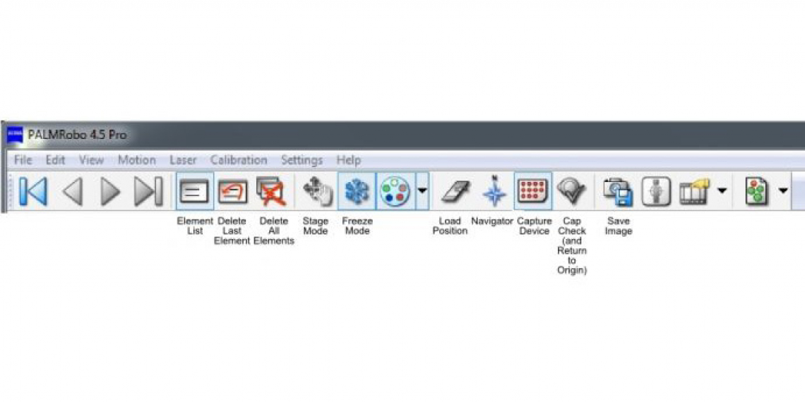
1. Either push back the light arm of the microscope or click 'Load Position' in the toolbar to move the stage to load position. Secure the slide in the slide holder and make sure the sample side is up and the slide sits flat. When done, either return the light arm or click 'Load Position' again to return the stage to observation position.
2. Use the joystick to move the stage and position the sample right above the objective. The stage speed is adjustable in 'Speed' --> 'Scrolling'.
3. On the touch screen of the microscope, choose an objective. The 20x, 40x, and the 63x objectives on the microscope have correction rings. When using a standard glass slide (~1 mm thick), check and make sure the black line mark on the corrective ring is aligned with "1" on the lense barrel. For #1.5 glass coverslip, the mark should point at the dot.
|
Position
|
Magnification |
NA
|
Correction Ring
|
|
1
|
5X
|
0.25
|
No
|
|
2
|
10X
|
0.50
|
No
|
|
3
|
20X
|
0.40
|
Yes
|
|
4
|
40X
|
0.60
|
Yes
|
|
5
|
63X
|
0.75
|
Yes
|
4. When the system is powered on, the transmitted light (TL) on the microscope is turned on. The sample can be viewed both in the eyepieces and on the computer monitor. Light intensity can be adjusted with the wheel on the lower front of the microscope.
5. Focus on the sample
6. In the program window, choose 'AxioCamICc1' camera and check the box next to 'Auto Live'
The stage can be positioned through the following ways
- Joystick
- Arrow keys on the keyboard
- Scroll bars in the image window (below and to the right of the image)
- Pointing the mouse cursor at the edge of the image
- Click the Stage Mode icon and move the mouse of the image
- 'Navigator' function
- 'Centering' tool in the graphic toolbar and clicking a point that is desired to be centered.
Loading collection tubes
- Activate RoboMover by clicking the 'Capture Device' icon. 'Capture Device' will open in a separate window.
- In the 'Capture Device' window, click 'Change Collector'
- The collector will be moved to loading position
- Load collection tube(s) (demo on-site)
- Click 'Scan Collector Type'
- A diagram of the collector appears, click on the cap of a tube in the diagram to move the tube in collection position. A collection tube can also be selected from the graphic toolbar or in the 'Element List' (see later).
Cutting and Catapulting
- From the 'Graphic Tools' at the bottom of the window, select the type of laser operation for cutting and/or catapulting.
For membrane-mounted specimen, 'RoboLPC' is a commonly used combination of cutting and subsequent catapulting; For glass-mounted samples, 'Close cut+AutoLPC' and 'AutoLPC' are preferred; For line-shaped structure, 'LineAutoLPC' is usually used; 'Cut' or 'LPC' is for simple cutting or catapulting. - Select the drawing tool from the graphic toolbar, and draw region(s) on the screen. If it is a big area, 'Creates Grid Rectangles' to divide the area into smaller ones
- If multiple regions are defined, the regions (so called 'elements' in PALMRobo) can be easily managed in element list. Open the 'Element List'. All regions are organized in the list.
- Each element can be selected (also highlighted) by clicking on that row. Double-clicking on an element opens a window that laser operations can be further modified for 'function type', 'objective','collection tube', etc. Operations on multiple elements (regions) can be executed if those elements are selected while holding down the 'Shift' key on the keyboard
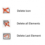
- The selected elements can also be deleted by clicking the icons in 'Element List', or simply using 'delete' key on the keyboard
Adjustment of laser power and focus
It is highly recommended that you test the power AND focus of the laser for cutting and/or catapulting before you start working on your interested regions. In general, the catapulting power is higher than the cutting power and the laser has to be defocused for catapulting.
- Use graphic tool to draw a 'Z' line in a homogenous area. In 'Speed' tools, select 'Cutting' and use a low speed
- Activate the laser, so the 'green' light dot becomes 'red'
- (To adjust laser power,) Start cutting and adjust the laser power by clicking on the arrows at the bottom of the 'Energy' column. Select the minimal laser power that generates a clear and fine cut
- (To adjust laser focus,) start cutting and adjust the laser focus by clicking on the arrows at the bottom of the 'Focus' column. Use the focus that results in a clear and fine cut
- Repeat the above steps if it is necessary
- Once a good cutting is achieved, add laser power and de-focus the laser for 'Catapulting'
(optional) Calibrating the laser marker when laser cuts don't align with the regions drawn
- Activate Stage Mode by clicking on the icon, or by 'F7' key
- Move mouse over the image and find a relatively homogenous region, then take your hand off the mouse
- Using the foot pedal, fire the laser
- Exit the 'Stage Mode' by hitting the 'F7' key again
- In the 'Menu Bar', select 'Calibration', then 'Laser Marker'
- A circular target shows up. Move and center the target over the point where the laser has been fired at. Left click your mouse.
- Done!
Check catapulting
- Click 'Cap Check' to position the stage and the objective. A lower magnification objective (e.g. 10x lens) can be used for this purpose.
- Raise the objective to focus and look for catapulted materials in the cap
- When done, click 'Cap Check' (now a 'Kill Cap' icon) to return the stage to the original location and original objective lens
Working with fluorescent samples
1. If a fluorescent sample will be observed in the eyepieces, on the touch screen choose the 'reflector' for blue (DAPI), green (FITC), or red (TR) fluorescence. Turn on the reflected light (RL), and in 'Light Path' choose 'Eyepiece'.
2. To show fluorescent images on the monitor, select the fluorescent camera port (the right port) on the touch screen. In the program window, select AxioCamMRm camera and enter an exposure time
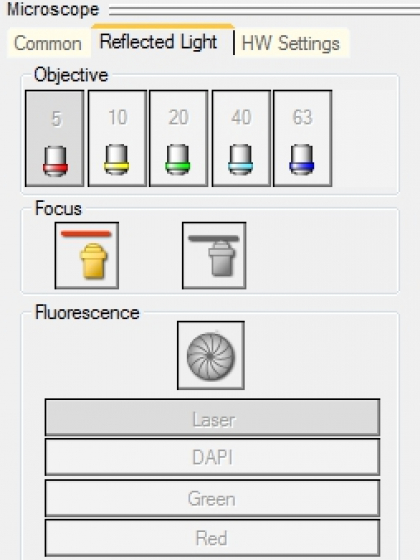
3. Find the 'Microscope' tools, click 'Reflected Light', select an illumination type (DAPI, Green, or Red), and click the 'shutter' icon to open/close the shutter
4. Make the image on the monitor in focus and click 'Freeze Mode' icon in the tool bar. The shutter will be closed to minimize the bleaching of the fluorescence in the sample.
5. Mark regions for cutting and/or catapulting on the image in 'Freeze Mode'
6. When ready to do cutting and/or catapulting, (1) click the 'Freeze Mode icon again to move out of 'Freeze Mode'; (2) on the touch screen choose '100% Mirror' as the light-path. Otherwise the cutting laser can't reach the sample.
Snapshot of image
Click 'Save Image' icon for a quick image-shot and choose a location to save the image
Check the online booking calendar to see if you should turn off the system or leave it on for the next user.
- Close the PALMRobo 4.5 Pro software
- If somebody is signed up in the next hour, please leave the whole system on
- If nobody else is signed up within one hour after you
- Close the program
- Return the collection tube adapter to storage box
- Shut down the computer from the start menu
- Turn off the controller box (Key from 'On' to 'Off')
- Turn off X-cite light (if you have used it)
- Switch off the power strips
- Cover the microscope (but not the hot light house)


