
Capabilities:
- Multiphoton imaging of thick in vivo and in vitro samples
- Long working distance objectives optimized for multiphoton
- Tunable fSec Ti:Saph laser (680-1080 nm) with pulse compensation
- 4 non-descanned detectors
- Tiled z-stack acquisition
- ScaleView imaging
- FLIM capability
-
Laser key switch to "on" (from standby, the laser lives in standby mode even if not used for a few days)
-
Fluorescent bulb (if you need it for eyepiece visualization)
-
Scope power supply
-
LCU box
-
Confocal electronic box (and make sure the key is turned to "on")
- PC on the right side - Login with LMCFuser account
If you want to do FLIM you also need to turn the left computer and PicoHarp300 box on the table.
Start the Olympus Fluoview software (FV10-ASW), at the pop-up box press ok to select LMCFuser (no pwd)
The system has 4 Non-Descanned Detectors (NDDs). These can be used in a few different configurations which need to be manually changed.
There are cubes for
- Blue, Green and Red - eg DAPI, GFP and mCherry (cube is marked MRVGR/XR)
- Cyan, Yellow and Red - eg CFP, YFP and mCherry (cube is marked MRCYR/XR)
These can be physically swapped by unscrewing the side panel with the two thumb screws on the left side and changing the entire cube module. Make sure it is pushed all the way to the back.
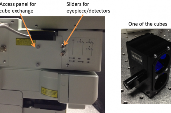
The detectors can also be used in 4-channel and 2-channel configuration. This is set by the sliders shown above -
- Both out = Eyepieces
- Both in = 4-channel mode (only 3 actually used)
- One in, one out = 2-channel mode
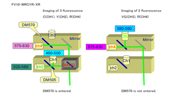
With the Blue-Green-Red cube in place the 4- and 2-channel options are these:
- Left picture: Blue to Channel 1, Green to Channel 2 and Red to Channel 4 (Ch 3 not used)
- Right picture: Channel 3 is a very broad band and Channel 4 is red

With the Cyan-Yellow-Red cube in place the two options are these:
- Left picture: Cyan to Channel 1, Yellow to Channel 2 and Red to Channel 4 (Ch 3 not used)
- Right picture: Channel 3 is a very broad band and Channel 4 is red
Place your sample on the stage, add water for optical contact and move the objective so it touches the water and is around 2 mm for the sample.
The down button on the rotary controller moves the objective down quickly. The speed of the rotary controller can be adjusted with the F/C button - Fine or Coarse which is displayed in the microscope panel of the software.
To use fluorescence light for eyepiece visualization
Click the EPI Lamp button and choose DAPI, RFP or GFP as appropriate.
The fluorescence can be turned off with RSHT button on the touch pad
To use transmitted light for eyepiece visualization
Click the Trans Lamp button in the software and turn on the Olympus LG-PS2 bulb
IMPORTANT - Turn off the LG-PS2 unit before starting to scan
Push in the sliders as appropriate for 2 or 4 channel acquisition.
Install the Photonic Isolation Device (bit of cardboard) around the scope, door closed, lights off
Tune the laser to correct wavelength by clicking on the green number in the laser panel. The check box should be checked so the laser shutter is open. If the box isn't green the laser has a problem.


Select the detectors as appropriate - RXD1 to 4. Make sure AutoHV is selected and the PMTs are in Analog int mode (if they are in photon counting mode the HV is greyed out)
XY Repeat starts scanning. (Focus X2 and Focus X4 focus more quickly by skip half or 3/4 of the lines). Focus and zoom if required.
Adjust detector gain (called HV in the Olympus software - high voltage on the PMT) and offset. You can mouse over the blue bars and use the mouse wheel to make these adjustments. The Gain is just a digital multiplier so probably leave that as 1.
Ctrl-H give you an under-over LUT for adjustment. Press ctrl-H again to leave this mode otherwise it saves the data in this scheme.
Enable the Kalman Filter Mode for averaging or the scan speed can be also be adjusted to improve SNR.
To acquire a single 2D image press the XY button and the data will appear in the 2D Views window.
Focus up and down and set top and bottom:
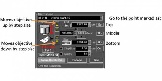
Choose the number of slices or interval.
Click Depth below the XY acquire button to enable to Z-stack acquisition and click the acquisition button to start the scan

When it is finished this box pops up and asks - series done (finish) or Append Next (take n additional slices)
You can scroll through the plane or make a MIP. Right click on the image and "Add view" to see overlay

Bright Z allows you to change the laser power and detector gains/HV with depth into the sample. Set several points at different depths and the software interpolates between them. Don't close the window otherwise the software will ignore these values and use a single value for the entire range.

The software can control the motorized stage to tile together stacks of images to allow imaging of a large area. The acquisition parameters are the same for each XY position so the first thing to do is set the z-stack and all settings as you would normally but suitable for all the XY positions.
It is recommended to zoom to around 1.5 to get better stitching as the edge of any objective is less uniform than the center. Don't use rotation - this should be at 0.
From the top menus: Device/Multi Area Time Lapse
A warning box pops up - "This stage will move in a wide range to detect the mechanical origin"
IMPORTANT: Click Cancel. Click OK if you want to calibrate the stage to find the 0 coordinate - but make sure your sample is removed and the checkbox for "Escape Automatically" is checked otherwise the very expensive objective may be damaged. It is not necessary to calibrate the stage for normal stitching use.
Two boxes appear
- Multi Area Time Lapse Controller
- Registered Point List

The MATL controller shows a map of the stage - mouse wheel to zoom in and out, double click to move to a point. You have two ways of specifying your XY area to tile
A. Define Matrix - n by n tile array centered on your current location
B. Mosaic Outline - define the edges and the software calculates all the positions to acquire
The Stage Controller box is useful to use for B, or you can use the joystick. If you have a complex shape you can define points around the edge of the shape and the software calculates the number of fields to acquire. Blank areas are not acquired but filled with 0 value pixels to produce a rectangular image at the end.
Preferences (icon above)
- Mostly default values are ok here so not much to change.
- Index size - this is the overlap. 100% = no overlap, the tile size is the same as the image size. 90% gives 10% overlap etc. Having some overlap allows a post-acquisition alignment of the images based on the structures within the sample. 5-10% overlap is a good starting point.
Press the Multi Area Time Lapse (MATL) Viewer so the viewer is open when data is acquired. (The first image displayed that is built as the images are acquired is not stitching just abutted so if you have overlap included this may look slightly odd).

- In the registered point list - click the save File and Folder icon to specify where the data goes to.
- Ready - creates fold structure and calculates the timing
- (if you adjust any settings the Re-register button should be pushed)
- Press the arrow to begin the acquisition
The images are saved individually as the acquisitions runs. The software is able to stitch these together based and stage position and tweak the alignment based on image structures. In the MATL viewer . . .
Open the MATL log file
Action/stitch . . . .
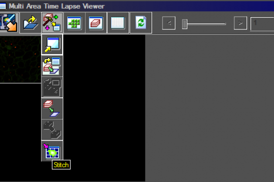
Choose a central Z-plane and click "Show"
Correction - when enabled this adjusts the alignment of the image based on
Smoothing - smooths the overlap
Press Open and save your image when prompted with the "series" checkbox checked
Adjustment images go to the Live View window and are not saved
Acquired images go to 2D views and appear as tabs.
Right click on the image you want and click save-as and it will store the data as a .OIB file (opens with FIJI) to
D:/FV10-ASW/Users/LMCFuser/Image/YourFolder
It is best to save the images as you go in case of a software crash. There is also a .OIF format where the data are stored directly to the hard drive for long time lapse/z-stack.
Please clean the objective gently with lens paper and record your use of the system using the CoreResearch booking system
If someone is scheduled within 1 hour -
-
Leave the system as is - don't close the software as it turns off the laser
If you are the last person of the day or nobody is using the system for at least an hour.
-
Close software
-
Shut down the computer from the start menu (please do any updates available)
-
Switches 5 (can leave the key as on), 4, 3 and then 2
-
Laser keyswitch to standby
When you leave please leave open the sliding door as it helps the air circulate